Challenge
- Pipeline inspection in vapor or partially-submerged, flammable vapor
- Inspection criteria: various (10CF192, 10CFR195, ASME FFS-1, NRC license renewal obligations, other ASME code, etc.)
- Acceptance criteria: identification measurement, and characterization of anomalies
Solution
- Utilize Diakont’s 8-14” robotic tooling to inspect the pipeline’s interior.
Results
- A detailed report of the inspection project, pipeline feature list, anomaly tally, snips of NDE data, graphs, photos, and videos, were provided to the customer with potential anomalies and measurements.
- This report is also used to perform engineering analysis’s regarding the condition of the lines and objects of the inspection project.
Inspection Requirement
For many years, inspection of piping and pipelines was limited either to using “free-swimming” flow-driven inspection tools (“pigs”), or performing inspections manually using hand tools such as UT probes.
The free-swimming pigs, typically with UT, MFL, or geometry sensors, are quite useful in that they can cover a long distance, and in some cases operate while the piping is in-operation with its normal transport contents (whether liquid or vapor). However for shorter piping lengths such as inside facilities, extensive pumps and piping modifications may be required. On longer lengths special launchers and receivers (“traps”) are generally installed, either temporarily or permanently. In either scenario, the piping or pipeline geometry and features must be able to accommodate the tool without it getting stuck. It is generally not possible to stop or reverse the tool partway through the inspection.
It is also possible to inspect piping from the outside using a hand scanner or “bracelet” probe, however this method is obviously only reasonable for short distances of piping, and it must be accessible by personnel from the outside.
The integrity of piping assets must be assured, for safety and environmental compliance, and also to meet regulatory and code requirements. Piping is generally operated at a pressure above atmosphere; for example, large-diameter natural gas transmission pipelines may operate above 1000 psi. Liquid pipelines must be able to withstand substantial pressure transients from multi-phase scenarios. Many pipelines carry hazardous or flammable contents that can cause explosion or ignition, or substantial environmental damages. A piping failure inside a facility can cause damage to personnel and other assets within the facility.
These inspections may be performed for a variety of reasons, including the following:
- Meeting regulatory or code requirements
- Performing secondary, higher-resolution inspection following a free-swimming ILI run
- Performing inspection following initial installation, particularly following HDD
- To assess condition of line in preparation for a change in service, or potential abandonment
- Performing special inspection following a failure, to determine the extent of condition
- To assess condition and also special geometric parameters of the piping in preparation for remediation (pipe-in-pipe, SIPP or composite repair, etc.)
Asset Details
Pressure piping and pipelines are built in wide variety of configurations.
Pipelines are generally located below-grade, although may sometimes be above grade and even over aerial crossings. They typically run horizontal to grade, although this may still result in substantial vertical angle changes. Bends and tee-connections may be welded forged elbows, may be field-fabricated, or may just be pipe routed in a curve over a certain long radius. Valves are typically full-diameter ball-style, although this may not always be the case. Reducers may or not be concentric. And tee-connections may or may not be barred.
Piping in facilities such as refineries, compressor stations, and power plants may include all of the above; and typically have more complex geometry than longer-distance pipelines.
The most common material for piping is carbon steel of various grades, although piping can also be stainless steel, cast iron, concrete, or concrete composite. Piping may be internally lined with mortar, or epoxy or other materials. The piping exterior may be coated with materials such as coal tar, wrapped, or may be encased in concrete. Piping may be in the soil, or inside buildings.
Pipe contents in operation may be petroleum liquids, natural gas (methane), crude oil, water, or any variety of other liquids, gasses, and even slurries. The interior surface may contain foreign material, and there may also be the presence of corrosion scale.
Inspection Technology
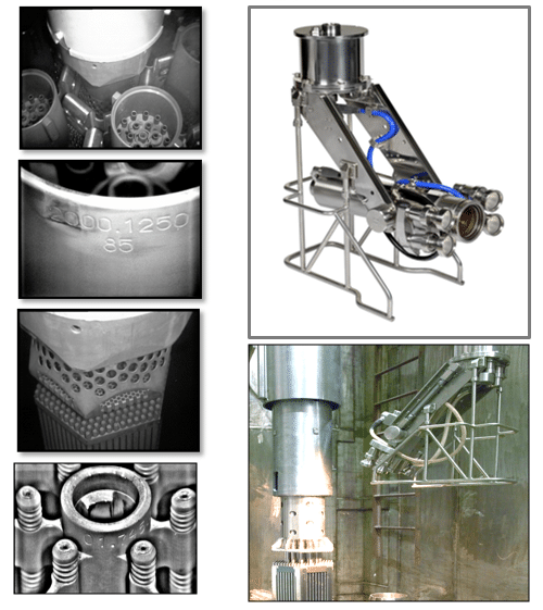
Diakont began the development of tooling and started providing robotic inspection services of piping in 2004, originally in the complex geometry and single-valve-isolated piping of gas compressor stations. Diakont now has a family of modular tools for varying conditions and pipe diameters, deployed on a global basis.
These tools are all robotic and mostly tethered in nature, for use when the piping is depressurized. They are semi-autonomous, with operators controlling the tool from a base station some distance away. The tethered tools can be deployed from an entry point to a distance of up to approximately ½ of a mile. The robotic tools accommodate bends, tees, vertical sections, and reducer transitions. They may be certified for use in hazardous environments with flammable vapor, and partially full of liquid. They deploy NDE technology that is suitable for the objectives of the inspection, and the pipe material and condition. These NDE payloads may include remote visual, EMAT-UT, PEC, ACFM, or laser scanning.
A separate control system provides power and control, and collects NDE data. Localization feedback comes from encoders and accelerometers. NDE scanning is automated.
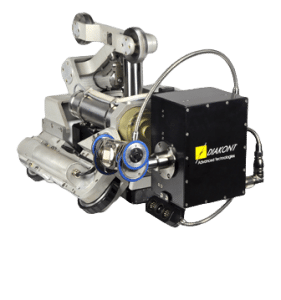
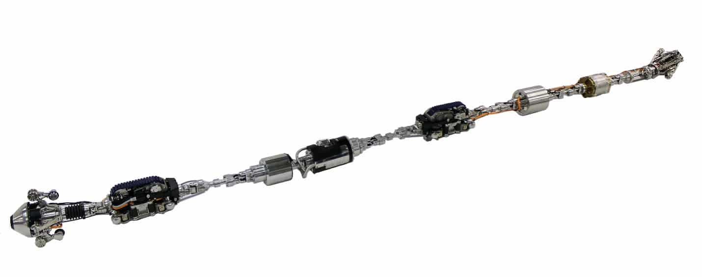 Diakont 8-14” Robotic Tool
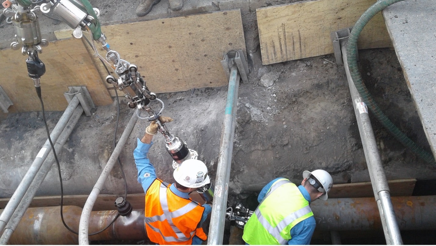
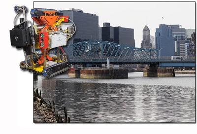
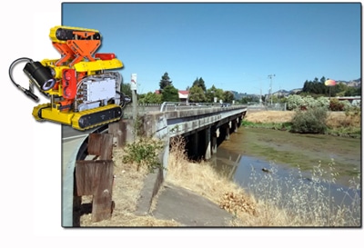
Robotic Tool Launch into Natural Gas Transmission Pipeline
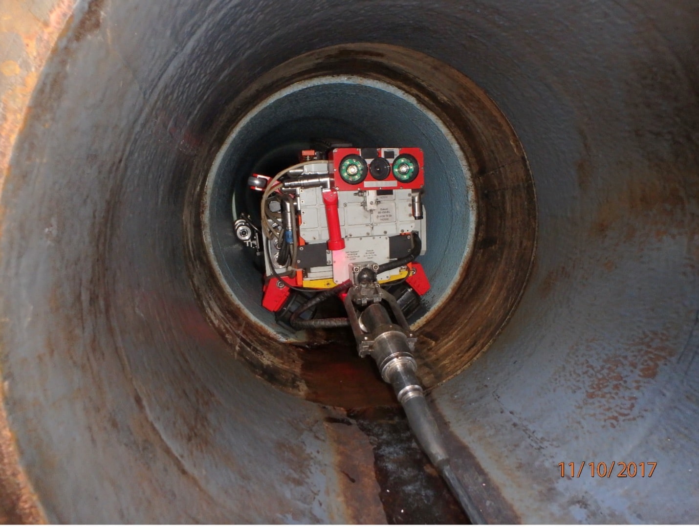
Robotic Tool Entering a 22” Pipe-in-Pipe Section to Perform an EMAT-UT Examination
Inspection Operation
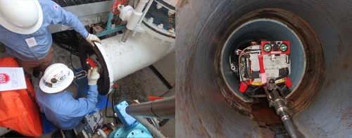
Inspection is typically performed by launching the robotic tool into a pipe via a removed valve, blind flange, or open face. Prior to launch, NDE sensors are verified and/or calibrated. The tool then traverses to the inspection area, which may comprise the entire distance from a launch point, or may be a shorter segment some distance away. Pipe features are logged as they are identified. The robotic tool is retrieved in the similar matter to how it was launched, followed by re-verifying NDE sensor performance.

Launch of a Robotic Tool on a Natural Gas Pipeline River Crossing
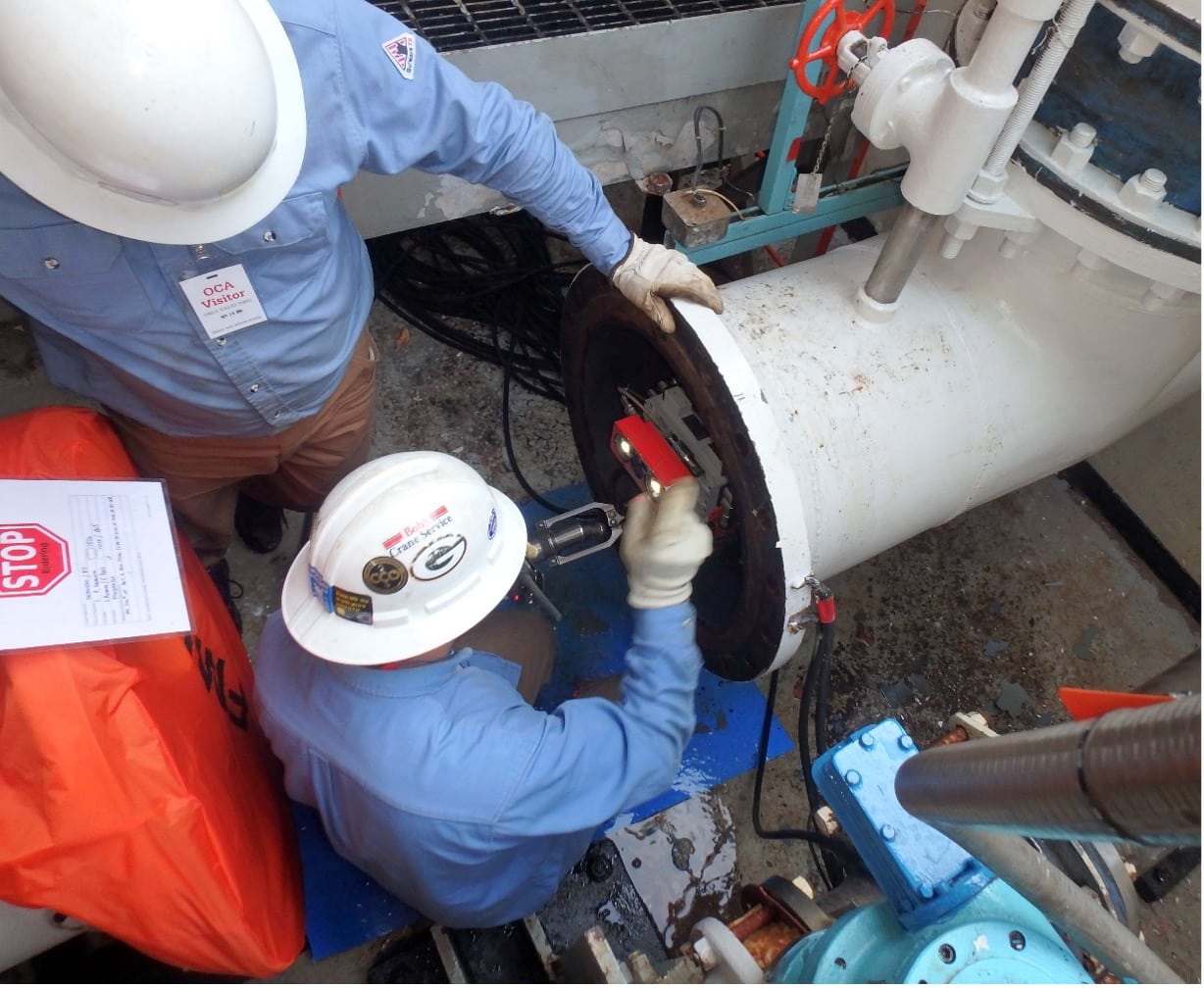
Launch of a Robotic Tool into Coolant Water Piping at a Nuclear Power Plant
Results
NDE data is analyzed and reported to the asset operator or other contracting entity following the project. This includes a description of the inspection project, and may include a pipeline feature list, anomaly tally, snips of NDE data, graphs, photos, and video.
This report is often then used to performing engineering analysis of the condition of the line, in accordance with the objectives of the inspection project.
Challenge
- Inspect an aboveground petroleum storage tank built to API 650.
- Environment: submerged, petroleum, flammable vapor, magnetometer and GPS-denied, zero visibility.
- Inspection criteria: API 653.
- Acceptance criteria: determine the remaining service life of the tank’s floor plates prior to repair or replacement.
Solution
- Utilize Diakont’s Stingray System inspection tool to inspect the tank’s floor, which was 80’ in diameter and 40’ in height, with a fixed cone roof supported by seven internal columns.
Results
- The scanned coverage exceeded what was planned. 96% of the total floor area was scannable, leaving the areas under the base plates from the seven support columns and floor-mounted drain lines unscannable due to the inability to access.
Inspection Requirement
In this case study, a Salt Lake City, UT refinery operator had an aboveground petroleum storage tank as part of one of their process units that was due for its required inspection based upon the facility’s Risk-Based Inspection (RBI) program. Due to the process flow within the unit, taking this particular tank out of service for a several-week turnaround would have had substantial negative impact on production. Considering that the tank was expected to be in sufficiently-good condition that would allow extension of the operating cycle under the parameters of the RBI program, the facility operator made the decision to evaluate conducting the required in-service API 653 inspection while the tank remained filled and in-operation.
The operator first had their embedded NDE contractor perform external manual assessments of the integrity of the shell, roof, and external appurtenances. Once these were determined to be in good condition that would support extension of the operating cycle, the facility then proceeded to plan the inspection of the floor plates.
Asset Details
This tank was constructed from steel to API 650 requirements. It was 80’ in diameter and 40’ in height, with a fixed cone roof supported by 7 internal columns. The floor plates were of typical construction with lap welded plates. This tank did not have an annular ring. The internal floor and lower portion of the shell was coated with a thick epoxy-based liner.
The tank contained unfinished diesel, with frequent flow and level changes. There was a thin (<1”) coating of sludge spread across the tank floor. Visibility within the tank was near-zero.
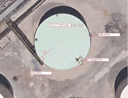 Tank overview
Inspection Technology Selection
A purpose-designed tank floor inspection crawler method was selected by the facility operator for conducting this project. Since the tank floor plates were in contact with the soil and supporting the liquid, access to the plates was only possible from inside the tank. Alternative indicative methods such as acoustic emission did not provide sufficient NDE resolution to satisfy the requirements of the RBI program administrator. The environment in the tank required safe, effective operation while submerged in petroleum and solid sludge, with access through an area of flammable vapor, and operation with no guidance from visual, GPS, or magnetometer sensors.
The facility operator considered multiple robotic NDE service providers for this project. The chosen technology was selected based upon:
- Meeting legal requirement of having NEC Class 1 Division 1 certification by a regulated body, for electrical equipment or umbilicals operating in the vapor space in the tank above the liquid level
- Having validated NDE technologies that met the API 653 requirements through a proven statistical analysis and real-world validations, with same or better effectiveness and coverage than would be achieved in a traditional out-of-service inspection
- Being operated by a robotic NDE service provider that was well-trusted, with certified quality system and ASNT-compliant operator qualifications
The facility operator selected Diakont to perform this inspection project, using their Stingray robotic tank floor inspection system. The system consisted of a 4-wheeled robotic crawler tool that traverses the tank floor, deployed into the tank from a hoist structure temporarily mounted to a roof manway hatch. The robotic crawler is equipped with 2 different NDE systems – both Magnetic Flux Leakage (MFL) and a 96-element array of immersion UT probes. The “critical zone” area adjacent to the floor-to-shell weld is interrogated to within the requirements of the standard. Travel is encoded, and orientation is maintained using fiber-optic gyroscopes. The tool is connected via an umbilical to a control station in a modular container away from the tank. Control software performs Simultaneous Localization and Mapping (SLAM), such that a tank floor map is built as the floor is scanned, plate-by-plate. The system operates in a semi-autonomous mode, with a Level II NDE Technician monitoring tool and NDE operation. Multiple video cameras on the tool record roof and coating condition, and are used for obstacle avoidance in clear (e.g. gasoline, alcohol, jet fuel) liquids. Obstacle avoidance in tanks without visibility (e.g. diesel, crude oil) is performed using 3D imaging sonars on the front and rear of the robotic crawler tool. Concurrently with the exam, internal out-of-plane settlement is measured, as required by the standard.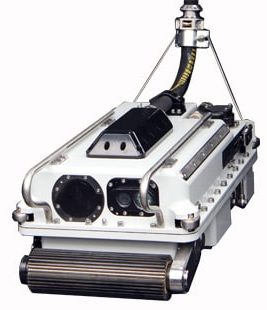
Diakont Stingray System Inspection Tool used in this project
Inspection Operation
To complete the inspection, the equipment was mobilized to site and staged. Electrical elements were bonded and grounded. Checkout and “cal-in” (verification) of the NDE systems were performed. The tank fill valve was temporarily blocked and locked/tagged-out (leaving suction in operation), and the permit for the inspection was issued.
The in-tank equipment and launcher were then raised to the tank roof via crane, along with liquid containment berms for use on retrieval. The manway hatch was removed, and the launcher was affixed to the manway flange.
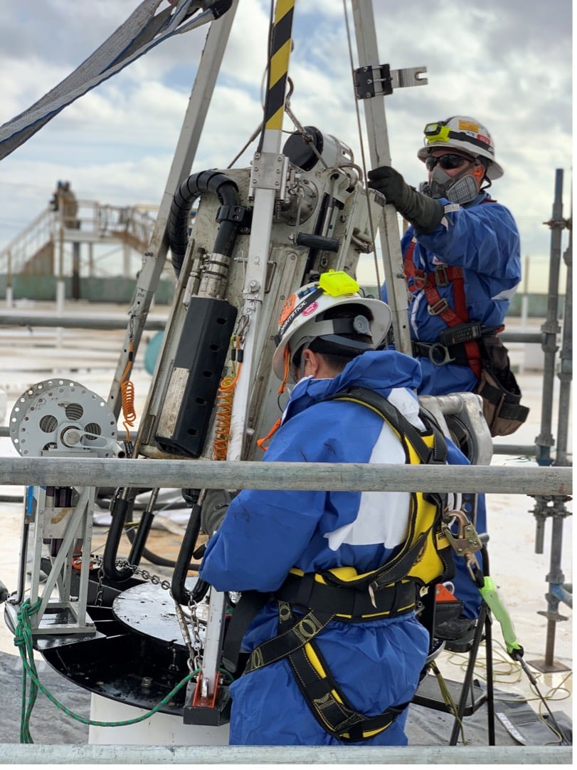 Technicians preparing for tool launch from roof (comparable photo from different tank)
The tool was then lowered into the tank, and while doing so a general visual exam was performed of the viewable area of the roof underside, to look for evidence of corrosion and condition of coating. The tool was then lowered to the tank floor. The temporary manway hatch seal was closed, the technicians secured the roof, and returned to the control station. At this point the tank fill valve was unblocked, so that the tank could resume full operation.
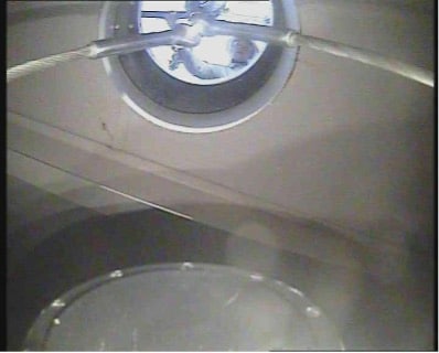 View of the roof underside
The inspection was conducted over the next days, on a plate-by-plate basis. The MFL and UT were used in parallel. The MFL was the detection NDE technology, providing a very robust NDE technique that tolerates topside corrosion and sludge which would cause signal loss with other methods such as PAUT. The UT array provided high-resolution absolute measurement and profiling of detected anomalies. Over 90 million UT A-scans were recorded.
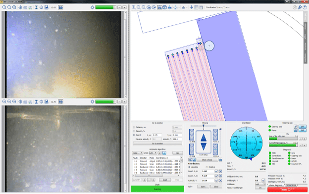 Operator screen showing autonomous planned motion path and heavy sludge on camera views
Results
The inspection was completed as-planned. The scanned coverage exceeded plan, with 96% of the total floor area scanned; just the area of the base plates under the 7 support columns and the floor-mounted drain line were not scanned due to not being accessible.
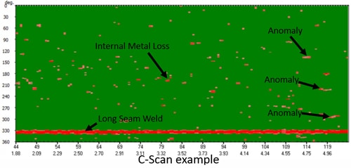
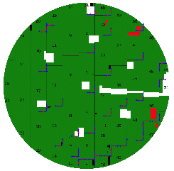 MFL encoded C-Scan display of mapped tank floor (Green area is above reporting threshold thickness, red is anomalous, and white is unscanned due to obstacles)
The initial results from the inspection were delivered to the facility operator in a preliminary report shortly after the inspection. A final report with complete analyzed results and assessment were delivered 30 days following demobilization from the site.
The facility’s API 653 inspector used the results of this inspection, plus the other external inspection data, to complete a comprehensive report on the tank that was required to meet corporate and state regulatory requirements. The tank floor and the balance of the tank were in quite good condition, such that the RBI program allowed extending the operational period of the tank for 15 additional years. Between the savings from avoiding the out-of-service turnaround, and avoiding the loss of productivity – the facility operator estimates that their same-year cost savings was approximately $1.1M.
Scheduling a storage tank outage to comply with regulations and industry standards can be inconvenient, especially when trying to align inspection schedules with repair schedules and customer expectations. Diakont has developed an inspection system to provide comprehensive storage tank floor inspection services while the tanks remain filled and operational to simplify tank inspection and maintenance. Certified Diakont inspection personnel use non-destructive testing (NDT) sensors and high-definition cameras on the crawler to deliver complete API 653-compliant inspection coverage.
Challenge
- Inspect four Chevron water tanks and a kerosene tank to deliver a complete API 653 compliant inspection coverage, while keeping tanks filled and operational.
Solution
- Utilize Diakont’s Stingray inspection system to minimize human risk during mandatory inspections and site operations while maximizing tank availability.
Results
- Diakont successfully demonstrated the Stingray tool launch, operation, and retrieval in all four tank inspections. The inspections navigated around the complex system of fire suppression piping and supported a site initiative to minimize human entry into confined spaces as well as being API 653 compliant.
Tank Entry Costs (Financial and Human)
Traditional storage tank inspections require inspectors to enter and occupy the tank for the duration of the inspection. Because this requires tank operators to drain, clean, and ventilate the tank, traditional inspection incurs both the actual cost of all operations and the opportunity cost of the tank being unavailable for use. Any personnel who enter the tank during the outage encounter confined space and hazardous substance hazards. The US Bureau of Labor Statistics reports 166 confined space fatalities in 2017 (an increase of 15% over 2016) as well as 531 fatalities due to harmful substance or environment exposure. Additionally, hazard communication, respiratory protection, and LOTO were three of the top five most frequently cited OSHA standards violated in 2018. The ability to inspect tanks without draining them will save storage tank operators substantial money, improve site safety, and maximize operational efficiency.
Robotic Inspection Service
The Stingray crawler is designed to inspect storage tanks up to 190 feet in diameter and 80 feet tall. Technicians deploy and retrieve the crawler via a device that bolts securely to a manhole on the tank roof; during the inspection, this device covers the manhole, preventing hazardous vapors from escaping the tank. The system is also explosion-proof certified for use in hazardous environments. The crawler combines magnetic flux leakage (MFL) and ultrasonic testing (UT) modules to ensure tool coverage complies with API 653 requirements. Unlike traditional inspections, which promise a full MFL scan but only use a secondary technology to confirm questionable findings, technicians use both NDT modules to gather data for the entire tank floor. In addition to ensuring all anomalies are located and measured, this additional data allows Diakont data analysts to provide accurate metal thickness readings for use in structural integrity efforts. Cameras on the crawler provide a view of the tank interior where conditions inside the tank permit. The crawler is also equipped with 3D sonar units to help technicians navigate in limited visibility as well as locate plate lap welds, the tank shell, and objects in the tank (e.g., roof drains, floating roof legs, the sump).
Service Value
- The Stingray completely eliminates lost revenue and increased costs inherent to service outages:
- Tank operators can schedule a Stingray inspection at their convenience rather than change their turnaround schedule to include a traditional inspection.
- Deploying the Stingray into a full tank to determine floor integrity helps optimize maintenance budgets by ensuring tanks are emptied for service only when necessary.
- Technicians climb onto the tank roof only to launch and retrieve the crawler, and never enter the tank. The Stingray’s remote operation eliminates the need to clean the tank or ensure tank interior safety for human entry, reducing inspection costs by up to 90%.
- Gaining inspection data prior to a planned outage rather than during the outage helps operators optimize project efficiency and further reduce turnaround time. The 600-foot long umbilical cable helps Diakont place the control station per operator preference to maximize inspection personnel safety and minimize inspection impact on other site operations.
Case Studies
Diakont successfully demonstrated Stingray tool launch, operation, and retrieval in three water tanks in 2017. Two of these water tanks were coordinated with Chevron and executed on Chevron property to confirm tool operation in a live work location. Diakont has subsequently used the system to inspect another water tank and a kerosene tank. The kerosene tank was coordinated with Chevron and executed on Chevron property to confirm safe operating procedures in hazardous environments (e.g., containment procedures during tool retrieval). As of 19 February 2019, Diakont has deployed Stingray equipment at a Chevron location for use in a diesel fuel tank. This inspection seeks to implement lessons learned during work at the kerosene tank as well as confirm work procedures in cold weather environments. Diakont also used the Stingray system in 2018 to inspect the steel floor of the secondary containment dike floor surrounding a benzene tank. This inspection demonstrated tool navigation capabilities around a complex system of fire suppression piping and supported a site initiative to minimize human entry into confined spaces.
Tank Operation Solution
Whether the tank floor requires a complete inspection or a condition assessment to support risk-based outage scheduling, Diakont’s Stingray inspection system minimizes human risk during mandatory inspections and site operations while maximizing tank availability.
Read More Tank Storage Magazine
References
1 National Census of Fatal Occupational Injuries in 2017. https://www.bls.gov/news.release/cfoi. nr0.htm. Accessed 19 February 2019.
2 Commonly Used Statistics. https://www.osha. gov/oshstats/commonstats.html. Accessed 19 February 2019.
Author:
This article was written by Tyler Powell, development program manager, Diakont Advanced Technologies. TPowell@diakont.us.com, www.diakont.com
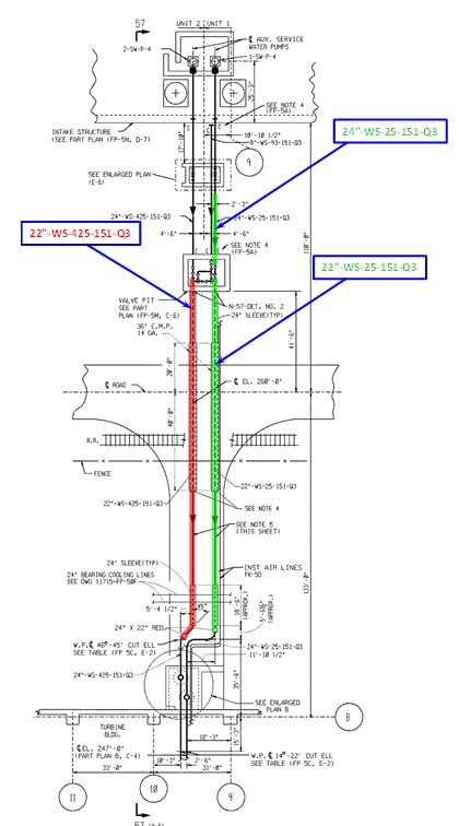
A team from Dominion Energy’s North Anna Power Station used Diakont’s robotic in-line inspection system (RODIS) crawlers to visually and volumetrically inspect auxiliary service water piping. These two lines provide an auxiliary feed from Lake Anna to the plant’s Service Water Reservoir. Portions of these lines were replaced in 1995, and the new 22” lines were sleeved through the two remaining 24” lines; therefore, excavation and visual inspection was not possible. To add additional challenges, these 22”-diameter lines are buried beneath a service road and a railroad track. Both lines have an internal ARC 855 multifunctional epoxy coating with a dry film thickness of 30-40 mils. The pipeline geometry included a concentric reducer that permits the 22” piping to connect to the remaining 24” piping which continues to the station’s turbine building. The team launched the RODIS tool via a valve pit near the intake structure at the edge of the lake. Figure 1 shows a diagram of the inspection area, with the areas inspected highlighted: the Unit 1 ASW line segments in GREEN and the Unit 2 ASW line segment in RED.
Challenge
- Visually and volumetrically inspect Dominion Energy’s North Anna Power Station’s auxiliary service water piping.
- The two lines were 22” in diameter and buried beneath a service road as well as railroad tracks, making them difficult and unpiggable.
Solution
- Implement Diakont’s RODIS crawler with three NDT inspection technologies. This eliminates the need for excavations and personnel pipe crawls while providing a complete volumetric exam of the pipe wall, enhancing station reliability and safety.
Results
- Diakont technicians successfully inspected a total of 141.9’of the pipeline.
- No anomalies were found within the pipe that exceeded Dominion’s reporting threshold of 12.5% wall loss, and the pipeline was put back into service following the inspection.
The specified primary objective of the inspection was to detect, characterize, and quantify the actual pipe wall thickness, any volumetric defects, and any internal or external corrosion in the inspection areas of the pipes. The secondary objectives were to detect and measure other anomalies of interest in the same areas as well as survey pipeline as-built features. The most important features of the EMAT technology is that the internal protective coating did not have to be removed for the inspection and a couplant was not required between the transducers and the substrate.
Robotic In-Line Inspection Tool
The Dominion Energy team selected an advanced robotic crawler that uses dual base tracks to navigate horizontal surfaces and a single top track to stabilize the crawler. The top track extends to the top of the pipe for additional traction while inspecting difficult pipe geometries such as vertical sections. An umbilical cable connected to a central control station provides power, real-time data collection, and control of the crawler’s tracks and sensor suite. A steel retrieval cable is also connected to the back of the tool for extraction in the event of a power failure.
- The RODIS crawler used at the North Anna Power Station employed three NDT inspection technologies:
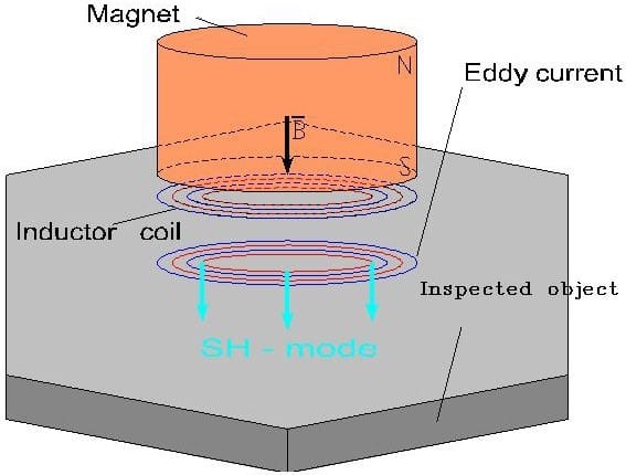
- EMAT ultrasonic testing sensors to measure pipeline wall thickness and locate corrosion damage on both the OD and ID. Figure 2 illustrates the operating principles of EMAT.
- A laser profilometer to make a detailed map of the pipeline’s inner surface, including pitting corrosion and other irregularities, and take fine measurements of individual internal diameter (ID) anomalies.
- A video camera suite to create a video record of the pipeline’s interior.
Unlike conventional UT instruments, EMAT sensors do not employ a couplant to transmit signals between the transducers and the pipe wall, making it ideal for pipeline inspections where foreign materials within lines are avoided at all costs. Diakont technicians configure a working gap between the EMAT transducers and the pipe wall before launching the tool to ensure optimal signal quality.
All sensor data feeds back to the inspection team in real time, allowing technicians to provide pipeline operators with same-day assessment results. The EMAT sensor used for this job was a specialized version with stronger magnetic fields to scan through the epoxy coating, as traditional EMAT sensors could not achieve adequate signal integrity.
Pre-Inspection Procedure
Before starting the project, the Dominion Energy team brought the Diakont inspection technicians onsite to receive industry-standard training and perform a site walk down. After analyzing the project parameters and pipeline geometries, Diakont technicians selected an appropriate RODIS crawler and NDT sensor suite to accommodate the inspection objectives. Diakont and Dominion also worked together to establish a personnel and safety plan.
In-Line Inspection
Diakont mobilized equipment onsite on the morning of August 4th, 2017 and performed system checks, including robot functions and NDT sensor calibration.
Dominion personnel used a crane to remove the concrete lid covering the valve pit to gain access to the auxiliary service water pipe system. Dominion then removed a valve from the area of interest and installed a blind cover on the pipe opening leading to the lake. A pipeline cleaning company performed a high-pressure water cleaning of the pipeline to remove any debris.
Diakont technicians hand-loaded the RODIS crawler into the pipe for a visual survey of the entire inspection length – recording video of the interior and surveying pipe elements. After the visual survey, technicians returned the crawler to the launch point and installed EMAT sensors to volumetrically inspect the pipe in automatic scan mode. Inspection technicians also manually drove the RODIS crawler to every indication of a potential defect for detailed characterization. Throughout the inspection, NDT data analysts reviewed the resultant data in real time, monitored tool operation via telemetry, and recorded precise pipeline geometric data, which was incorporated into a pipe tally in the pipe feature list report.
OLYMPUS DIGITAL CAMERA
Unlike conventional UT instruments, EMAT sensors do not employ a couplant to transmit signals between the transducers and the pipe wall, making it ideal for pipeline inspections where foreign materials within lines are avoided at all costs. Diakont technicians configure a working gap between the EMAT transducers and the pipe wall before launching the tool to ensure optimal signal quality.
All sensor data feeds back to the inspection team in real time, allowing technicians to provide pipeline operators with same-day assessment results. The EMAT sensor used for this job was a specialized version with stronger magnetic fields to scan through the epoxy coating, as traditional EMAT sensors could not achieve adequate signal integrity.
Pre-Inspection Procedure
Before starting the project, the Dominion Energy team brought the Diakont inspection technicians onsite to receive industry-standard training and perform a site walk down. After analyzing the project parameters and pipeline geometries, Diakont technicians selected an appropriate RODIS crawler and NDT sensor suite to accommodate the inspection objectives. Diakont and Dominion also worked together to establish a personnel and safety plan.
In-Line Inspection
Diakont mobilized equipment onsite on the morning of August 4th, 2017 and performed system checks, including robot functions and NDT sensor calibration.
Dominion personnel used a crane to remove the concrete lid covering the valve pit to gain access to the auxiliary service water pipe system. Dominion then removed a valve from the area of interest and installed a blind cover on the pipe opening leading to the lake. A pipeline cleaning company performed a high-pressure water cleaning of the pipeline to remove any debris.
Diakont technicians hand-loaded the RODIS crawler into the pipe for a visual survey of the entire inspection length – recording video of the interior and surveying pipe elements. After the visual survey, technicians returned the crawler to the launch point and installed EMAT sensors to volumetrically inspect the pipe in automatic scan mode. Inspection technicians also manually drove the RODIS crawler to every indication of a potential defect for detailed characterization. Throughout the inspection, NDT data analysts reviewed the resultant data in real time, monitored tool operation via telemetry, and recorded precise pipeline geometric data, which was incorporated into a pipe tally in the pipe feature list report.
Diakont was commissioned to assess the integrity of three major North American large diameter natural gas pipelines that crossed beneath rivers. The pipelines had multiple bends and low-flow, making them ‘unpiggable’ using traditional in-line inspection (ILI) methods. They also required the use of a tethered device to guarantee a successful retrieval. Each pipeline inspection case had unique characteristics that required specialized robotic solutions. The following sections provide details for each case study.
Challenge
- Assess the integrity of three major North American large-diameter natural gas pipelines that crossed beneath rivers.
- The pipelines had multiple bends and low-flow, making them ‘unpiggable’ using traditional in-line inspection (ILI) methods and required specialized robotic solutions.
Solution
- Utilize a variety of Diakont’s robotic ILI crawlers that were equipped with specific features specifically selected for each pipeline’s environment.
Result
- All three pipelines were able to be put back into service after inspection, some resulting in minor metal loss therefore documented for monitoring degradation.
Mississippi River Crossing

Diakont was commissioned by the pipeline operator to further investigate an anomaly previously found by a traditional in-line inspection. The 18” natural gas steel pipeline ran beneath the Mississippi River and had a known dent that was detected by a flow-driven smart pig. Unfortunately the downward angle of the pipeline caused a speed surge of the pig run and the details of the dent’s location and characteristics were unknown. Diakont selected an 18” robotic crawler to inspect the pipeline. Diakont hand loaded the robotic ILI crawler into the pipe via a removed spool near the edge of the river. The inspection team drove the crawler beneath the river crossing and identified the dent at 1,170 feet in the pipe. The inspection team then used EMAT NDE sensors to characterize the dent and verify the actual pipe wall thickness. The NDE scan revealed that there was 0.03” metal loss on the OD of the pipe at the location of the dent. The remaining wall thickness was within the allowable operating limits for the pipe section and the line was put back into service.
Passaic River Crossing
Diakont was commissioned to inspect a multi-diameter pipeline that traversed beneath the Passaic River and a railroad track. The natural gas steel pipeline had a diameter of 26” at the beginning then expanded to 30” half way through the line. The total inspection distance was 1,500 feet and contained multiple bends. To handle these inspection requirements, Diakont used a multi-diameter robotic ILI crawler equipped with three track systems connected to actuation systems. After scanning through the first section of the pipeline, inspection technicians raised the crawler tracks to accommodate the 30” pipeline diameter. The inspection revealed three areas of external corrosion with minor metal loss. These sections were documented for monitoring degradation over time and the pipeline was put back into service.
Novato Creek Crossing
Diakont was commissioned to inspect two pipelines that ran beneath the Novato Creek. The two lines, with diameters of 16” and 20”, were natural gas steel pipelines that contained extreme geometries including 90° bends, back-to-back bends, and vertical sections. The lines were also constructed with thicker than normal pipes which required a unique NDE assessment technology. Diakont selected two robotic crawlers to handle the inspection project. Each crawler had track systems equipped with actuation systems that pressed the tracks into the ID of the pipeline to provide the traction required for bends and verticals. Using high-power EMAT sensor suites, Diakont’s robotic ILI crawlers inspected the entirety of both lines. The inspections revealed that both pipelines were in good condition with only two minor anomalies. The pipelines were put back into service following the inspection.
Challenge
- Inspect an 18” high-pressure coolant injection (HPCI) buried line at the Cooper Nuclear Station.
Solution
- Use Diakont’s patented Electro-Magnetic Acoustic Transducer (EMAT) technology and customized robot to perform an inspection of the safety-related HPCI pipe section.
Results
- A 100% inspection coverage throughout the two 45-degree elbow fittings was completed.
- There were no critical defects detected, and the piping system was returned to service following the inspection.

Diakont, along with strategic partner Structural Integrity Associates, Inc., recently completed the group’s first buried piping in-line inspection project at a US nuclear plant. The inspection was performed in October 2012 on an 18” High Pressure Coolant Injection (HPCI) line at Cooper Nuclear Station. Utilizing a crawler tool equipped with Diakont’s patented Electro-Magnetic Acoustic Transducer (EMAT) technology, the team performed a 100%-coverage inspection of the safety-related HPCI pipe section. Inspection preparations by Structural Integrity included code-based, finite element analyses to establish the acceptance criteria in the event that metal loss was discovered, thereby minimizing any potential outage schedule impact. There were no critical defects detected, and the piping system was returned to service following the inspection.
The RODIS-18 inspection tool was developed specifically for this project, leveraging robotic and inspection elements from Diakont’s RODIS-28 tool. Modifications were made to accommodate the piping system diameter, and to provide 100% inspection coverage throughout the two 45-degree elbow fittings. Many of the robust design features of the existing technology were maintained, including the EMAT module, ensuring familiarity for the robot operators and NDE technicians. As part of the development and qualification process, a full-fidelity mockup was fabricated at Diakont’s facility to test robot navigation and EMAT operations, as well as to provide the required crew training. Structural Integrity was integral to the development and field implementation process, providing finite element analysis, commercial-grade dedication support, and data management using the BPWorks™ database.
 Edward Petit de Mange, Managing Director of Diakont added, “Diakont, working with Structural Integrity, proved to be a highly-proficient team for the HPCI buried piping inspection at Cooper Nuclear Station. Utilizing Diakont’s versatile crawler coupled with Structural Integrity’s project oversight and analysis, the team provided accurate, comprehensive inspection results within the tight outage-driven timeframe.”
Steve Biagiotti, PE, Sr. Associate and Nuclear Buried Pipe Product Manager for Structural Integrity shared his agreement. “The ability to perform UT remaining wall thickness examinations from the inside of a pipe using a single access point and without the need to excavate buried piping provides the nuclear power industry with a new tool in their arsenal to further assure stakeholders of the continued integrity of these systems. We are pleased to be working with Diakont on this endeavor to provide industry leading technology solutions.”
About Diakont
Diakont is a full-cycle engineering, manufacturing, and service company that provides high-tech solutions which enhance the safety and economy of the nuclear power and pipeline industries. With a North American facility located in San Diego, California, Diakont is a leading manufacturer of pipeline inspection robotics, digital I&C systems, fuel handling equipment, and radiation-tolerant camera systems. Diakont products are utilized worldwide on power plants of all designs.
About Structural Integrity Associates, Inc.
Structural Integrity Associates, Inc. is an internationally recognized engineering leader in prevention and control of structural and mechanical failures. Headquartered in San Jose, California, Structural Integrity serves clients worldwide with a dozen branch offices throughout the United States and Canada, as well as affiliates in China, Japan, Korea, and Spain. Structural Integrity’s expertise in buried piping programs and data management has helped nuclear power plants worldwide.
Diakont’s innovative refueling machines increase safety and performance of nuclear power plant operations. Since 2002, Diakont successfully delivered 35 upgraded refueling machine systems to nuclear power plants worldwide. The upgraded systems incorporate various automated features to handle simultaneous movements for reduced reloading time.
Challenge
- Reduce time on standard refueling operations during nuclear outages while increasing safety and performance.
Solution
- Implement Diakont’s modernized FHMs and advanced IMSS safety system with operational objectives that include:
- Safety assurance when performing all nuclear fuel transportation
- Digital control system upgrades to increase fuel movement efficiency
- Obsolete components replaced
- Extended operating life
Results
- Since 2002, Diakont has successfully delivered 35 upgraded refueling machine systems to nuclear power plants worldwide.
- This innovative refueling machine saves nuclear power plants 95 hours on average per outage during refueling operations
- An overall operational ease with reduced personnel dosage rate, reduced liquid radioactive waste, and a decreased need for clear borated water.
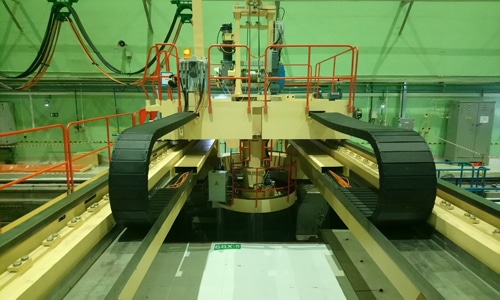
Optimized Structure Weight
Diakont’s bridge and trolley are optimized by weight to withstand extreme seismic effects. Diakont achieved a reduced weight by introducing several modern features. Separate drive trains, bridge seismic locks, and dedicated mast drives greatly reduces the weight by excluding the need for a comb rail and a number of kinetic train elements.
Seismic Locks and Guide Rollers
Diakont’s earthquake resistant fuel handling machines (FHMs) are capable of handling seismic category I situations and incorporate a 7-point safe earthquake shutdown system. During seismic influence, the seismic lock systems clamp down on the rail head to hold the fuel transfer machine still. A gapless contact is maintained with the bridge guide rollers to prevent the bridge position from skewing and increases positioning accuracy at specified coordinates.
High-Efficiency In-Mast Fuel Sipping System
Diakont’s In-Mast Sipping System (IMSS) is a proven process for identifying leaking fuel assemblies. Since 2004, Diakont successfully delivered 31 in-mast sipping systems to nuclear power plants worldwide. The system vacuums, or sips, gas from the around the fuel assemblies, whereby the presence of xenon and/or krypton is used to indicate leaking fuel. Diakont’s IMSS inspects 100% of fuel assemblies and guarantees detection of fuel assemblies with leaking rods. Using the IMSS greatly increases fuel operational efficiency and decreases the refueling time by an average of 4-5 days per reactor.
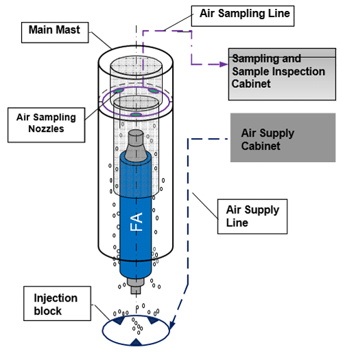
The IMSS operates by delivering compressed air under the liner of each fuel assembly. A gas sample is taken from the inner cavity of the FHM above the water level and is measured with a beta-activity meter.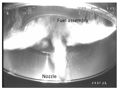
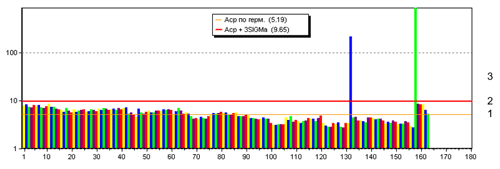
The following chart illustrates the beta-activity from a recent fuel assembly inspection using Diakont’s IMSS. Fuel assemblies 132 and 158 demonstrated beta-activity beyond the operational threshold and were removed.
Monitoring Fuel Handling Operations
Diakont’s FHMs use high radiation video cameras integrated on pan & tilt units to provide comprehensive monitoring of all fuel handling operations. The system is capable of 6x zoom and has built-in underwater illuminators. Screenshots illustrating the system’s image clarity in high-radiation environments are shown below.
Refueling Results from Diakont’s FHMs with IMSS
Diakont’s modernized FHMs and advanced IMSS safety systems greatly reduce refueling time by automated features to handle simultaneous movements. The following table illustrates the time saving results achieved from incorporating Diakont’s FHMs.
| Refueling Operations |
Refueling Performance of Legacy FHM |
Refueling Performance of Diakont’s FHM |
| Reloading of one FA from reactor to spent fuel pool |
40 min |
20 min |
| Reloading of one FA from spent fuel pool to reactor |
38 min |
23 min |
| Total reactor core unloading (163 Fas) |
108 hours |
55 hours |
| Total reactor core loading time (163 FAs) |
104 hours |
62 hours |
| Refueling time saving per 1 outage: |
95 HOURS |
Performance Results from Legacy FHMs vs Diakont FHMs
Using Diakont’s modern FHMs and IMSS, nuclear power plants are able to save an average of 95 hours on standard refueling operations per outage. Further, plant operators that invested in Diakont IMSS reduced personnel dose uptake, reduced liquid radioactive waste, decreased the need for clear borated water, and increased ease of operation.
BWR and PWR nuclear plant operators effectively reduce personnel dose by decontaminating the surfaces of the refueling cavity, dryer and separator pools, and components within these spaces. Plant operators have employed several methods to handle this task; however, the results vary in effectiveness for meeting ALARA and decontamination coverage goals. Faced with these challenges, many nuclear utilities are constantly seeking to improve decontamination methods and tooling.
For this reason, FirstEnergy Nuclear Operating Company (FENOC) approached Diakont to develop an improved underwater robotic decontamination tool. Some of FENOC’s requirements included operation in parallel with other activities, having the mobility to swim/navigate throughout the refueling cavity, adhering to walls, floors, and curved surfaces, and reliable and effective surface decontamination such that manual scrubbing is not required.
During the Spring 2017 outage, FENOC’s Perry Nuclear Power Plant in Ohio completed its first successful underwater decontamination using the newly developed decon tool, achieving its ALARA goals and saving time over previous methods.. Producing 1,268 megawatts of electricity (enough to power more than 1 million homes), the BWR-6 at the Perry site is one of the largest single-unit plants in the United States.
Challenge
- Decontaminate the Perry Nuclear Power Plant cavity during Spring 2017refueling outage.
- Reduce personnel dose exposure, radwaste, decontamination time, and cost from previous years without raising the risk of contamination spreading and altering plant chemistry.
Solution
- Use Diakont’s robotic decontamination tooling while cavities are flooded, in parallel with fuel movement and other activities.
Results
- A successful decontamination job resulting in no additional manual cavity decontamination after drain down. ALARA goals were also achieved while time and cost were saved from previous methods.
- Preliminary surveys indicated that all contamination levels were reduced to <50k dpm/100 cm2 helping the utility meet their INPO/industry collective radiation exposure goal as well as reduce personnel dose exposure.
- Plant personnel at Perry Nuclear Power Plant plan on using the tool to examine underwater boots next summer in the suppression pool.
Established Decontamination Methods
Historically, nuclear plant operators conducted cleaning and decontamination of refueling cavity surfaces by one of five methods: manual scrubbing, the use of strippable coatings, high-pressure washing, hydrolasing, and automated decontamination using robotic tooling. Each of these methods can be effective, but there are advantages and disadvantages of each.
Manual scrubbing is a straightforward procedure that doesn’t require expensive equipment or training, however, this method results in extensive personnel dose exposure, requires drain down, and the decontamination results can vary.
The use of strippable coatings is an effective decontamination method since the coatings seal any contaminants in place, which are then stripped away. This method is costly and requires trained personnel for the application and removal of the coatings. It also produces considerable radiological waste. The strippable coating is often applied manually, resulting in relatively high dose exposure during application, and generally requires curing time thereafter, making it one of the most time-consuming decontamination methods.
High-pressure washing is typically done from the pool edge using a high pressure (i.e. 3000 psi) handheld gun or wand which is held close to the decontamination surface. This method is quite widespread throughout the US nuclear industry, but it has disadvantages: the addition of water in the reactor cavity has the potential to alter chemistry, particularly impacting boron concentration in PWR plants, and has the potential to spread contaminants or create airborne activity.
Similar to high-pressure washing, hydrolasing also uses water to blast the cavity surfaces, except with much greater force. Using the greater force of the water jet, hydrolasing delivers decontamination results using less water, yet it still has the potential to impact boron concentrations in PWRs. The powerful jet can also cause personnel injury if used improperly.
Most automated decontamination systems perform reliable decontamination and require fewer staff resources than manual methods, resulting in greatly reduced personnel dose exposure. However, these tools only work on flat surfaces or require the constant use of an auxiliary hook, boom, rail, or primary overhead crane while performing decontamination. These tools also provide inconsistent decon results. Some of the tools require modifying the tool outside of the pool in order to switch from cleaning the floor to walls, and vice versa, and the brush change-out can be time consuming as well.
The underwater robotic decon solution developed by Diakont presents a substantial improvement over historical cavity decon methods because it can reduce personnel dose exposure, reduce radwaste, doesn’t impact plant chemistry, doesn’t risk inadvertently spreading contamination, and eliminates the risk of personnel injury and component damage associated with hydrolasing. Most importantly, by performing decontamination robotically while the cavities are flooded and in parallel with fuel movement and other activities, critical path schedule duration can be reduced. The self-propelled Remotely Operated Vehicle (ROV) -crawler solution does not require the constant use of bridge or crane after deployment. Unlike other robotic decon tools, this system is simple to use and plant personnel can be trained to operate it without the need to bring in outside vendors.
Remotely Operated, Self-Propelled Solution
The robotic decontamination tool deployed for FENOC is a hybrid ROV-crawler platform equipped with an integrated cleaning system. It operates and transitions freely between ROV “flying” mode, and “crawler” mode (for any orientation) with no physical adjustments required to the system. To accomplish this, the tool utilizes a flow-less vortex generator on its chassis that creates up to 60 pounds of suction force to adhere to flat and curved, horizontal and vertical surfaces, including interferences and seams. The crawler system is driven in a simple tank-like “skid steer” fashion and has 26 pounds of traction drive force that provides full control in flow conditions, as well as appropriate umbilical movement. When in ROV mode, six (6) identical brushless DC vectored and vertical thrusters provide versatile maneuverability and positioning.
The tool’s cleaning system is comprised of a shroud enclosing an integrated, fixed-force rotating cylindrical brush assembly connected to an existing vacuum submerged in the cavity, which filters the contaminated particulates dislodged by the brush. Rotational speed and downforce are adjustable for optimal performance. The system uses off-the-shelf brushes to keep costs down and the brushes can be exchanged for various abrasive grit sizes depending on the surface and level of cleaning required.
The decon tool also includes independent lighting and multiple camera systems for appropriate situational awareness and navigation. The entire tool utilizes mature, nuclear-proven, and foreign material exclusion (FME)-compliant subassemblies.
Robotic Underwater Decontamination Procedure
Before entering containment, the Diakont field engineer team completed an FME pre-check on the decon tooling and cables in a staging area. Once completed, the team set up the ROV-crawler control station on the refueling floor away from the edge of the refueling cavity, in a lower-dose space separate from other outage operations. After a complete system function check, the decon tool was connected to the vacuum pump in the cavity. The tool was then deployed into the water using the overhead crane, taking precaution to minimize disruption to the water surface. The team then cleared the shroud cavity of air bubbles by cycling the vacuum pump power, such that the vehicle was appropriately trimmed. The final step was the deployment of a high definition camera into the cavity to monitor decon operations and umbilical location from a bird’s eye perspective, to support the operator’s situational awareness.
The robotics operator navigated the decon tool in “flying” mode close to the wall and positioned the tool so either the port or starboard side was close to the wall. Then the operator rotated the tool until the track wheels touched the cavity wall and activated the flow-less vortex generator to adhere to the wall. The robotics operator next initiated the brush operation and performed surface cleaning by traversing up and down the wall in an overlapping manner, similar to vacuuming a carpet, while using the onboard and bird’s eye view camera to identify any obstacles in the way. A second operator, as needed, was positioned near the cavity edge and supported umbilical cable management.
After performing the decontamination passes on the first wall, the robotics operator disengaged the tool from the wall and operated the ROV in “flying” mode to navigate to the next area within the refueling cavity. This robotics operator repeated this procedure until all of the walls and floor were decontaminated. This particular decontamination project also included the curved surfaces of the drywell head. The decon tool’s brush speed varied in each section based on the level of debris – slower speeds were employed in areas with high levels of debris to avoid excessively disturbing the material. Field engineers monitored the process to ensure that the vacuum shroud effectively captured the dislodged debris. During this process, the robotics operator demonstrated the controls to plant personnel and had them operate the tool as well.
Immediately following the decontamination procedure, the field team prepared a staging area near the cavity edge with a containment receptacle and the necessary tools for decontaminating the decon tool and performing the brush removal. With the assistance of a plant crane operator, field engineers used the overhead crane with a pneumatic hook to hoist the decon tool out of the water and into the containment receptacle. To remove the excess water from the hose, technicians then turned on the pump momentarily before disconnecting the vacuum hose from the ROV
Finally, the field team cut off the consumable crawler treads and removed the brush from the shroud – these items along with disposable personal protective equipment (PPE) and wiping rags were the only radwaste from the decontamination procedure. Changing the brush out is very simple, requiring only two hand knobs to remove. Once the decon tool was wiped dry, the system was packed in an LSA (spell out) transit case per the site requirements.
Decontamination Results
At the Spring 2017 refueling outage at Perry Nuclear Power Plant, decontamination services were so effective that no additional manual cavity decon was required after drain-down. Using the tool’s ability to swim, attach, and crawl, Diakont decontaminated surfaces designated by the plant operator. Preliminary surveys indicated that all contamination levels were reduced to <50K dpm/100 cm2, helping the utility meet their INPO/Industry collective radiation exposure goals.
Additionally, the tool is modular and can be used without the brush assembly to perform visual inspections and can also be configured with different attachments to support many other underwater applications. Plant personnel at Perry Nuclear Power Plant are planning on using the tool to examine underwater boots next summer in the suppression pool.
Diakont was commissioned to assess the integrity of a major North American natural gas pipeline, which was partially buried under an urban area. The company used a reduced size robotic crawler to successfully navigate a 10 in. pipe. The size of this pipe has previously been a limitation, making it ‘unpiggable’ using other inline inspection (ILI) methods.
Challenge
- Assess the integrity of a major North American natural gas pipeline partially buried under an urban area. Given the location of the pipe, the low flow, narrow10-in internal diameter (ID),and pipeline characteristics (e.g., tight bends, plug valves) it had never been inspected and was unsuitable for traditional smart-pigging.
Solution
- Implement Diakont’s Sprinter tool created for challenging pipeline geometrics.It’s ability to navigate across horizontal surfaces and extend to the tracks of the pipe wall for stabilization, made it ideal for this job.
Results
- The inspection went smoothly and was completed within five working days–one less than predicted. The HCA pipe was in excellent condition with only a few minor flaws, allowing the pipe return to service promptly.
Narrow Pipe ID Creates Inspection Hurdle For HCA Pipeline
Designated as a high consequence area (HCA) due to being located in a densely-populated urban area, this section of pipeline had never been inspected; low flow, its narrow 10-in. internal diameter (ID), and pipeline characteristics (e.g., tight bends, plug valves) made it unsuitable for traditional smart-pigging. However, United States federal Pipeline and Hazardous Materials Safety Administration (PHMSA) regulations require specific integrity management programs in HCAs. The piping’s inspection challenges could have forced the pipeline operator to replace the entire quarter-mile length of pipe if they could not inspect the line on schedule. The technology gap between inspection requirements and available tooling forced the industry work with pipeline service vendors to develop a solution.
A Reduced-Size, Self-Propelled Solution
The HCA consists of 1325 feet of partially-buried line located near a library, a school, and private homes. Low flow, pipeline geometry, and a lack of sufficient access points prevented the use and retrieval of a free-flowing smart pig. For these reasons, an ILI solution was deemed necessary, but most existing self-propelled ILI solutions readily available on the market were too large to navigate the piping’s narrow ID. The operator determined that a smaller form-factor inspection crawler solution was needed to navigate the piping’s challenging geometry (including vertical sections and mitered bends) as well as to allow entry and retrieval from a single access point without the large footprint of a pig launcher/receiver.
Faced with these inspection challenges, the pipeline operator turned to pioneering engineering firm Diakont Advanced Technologies for a solution. The operator selected Diakont’s Sprinter robotic crawler tool for the inspection because of its ability to negotiate unpiggable pipeline geometries with IDs as small as 8 inches. The Sprinter accommodates small IDs by arranging the robotic crawler track modules, control electronics, and NDE sensor suite modules into a linear assembly. The robotic modules attach together via rugged flexible connections, giving the Sprinter remarkable maneuverability. The Sprinter inspection system is mobilized on-site in separate sections and assembled near the pipe access point to reduce the space required for the inspection crew and the impact to the pipeline operator.
Diakont’s Sprinter tool traverses challenging pipeline geometries using a ruggedized multiple-track system for navigation across horizontal surfaces, and the tool can extend the tracks to the pipe wall for stabilization. This arrangement provides the necessary traction to hold the tool rigidly in place while inspecting difficult-to-access pipeline applications where conventional ILI tools may not be feasible, including inclines and vertical sections. This Sprinter system moves at a deliberate pace to provide accurate mapping of anomaly locations within the pipeline. Self-propelled and bidirectional, the Sprinter can also be deployed and retrieved from a single access point, which was another key feature in its selection for this inspection.
Diakont’s Sprinter tool is equipped with an advanced non-destructive examination (NDE) sensor suite to provide comprehensive assessments of pipe wall conditions:
- Diakont’s patented ultrasonic testing (UT) electromagnetic acoustic transducer (EMAT) module measures pipeline wall thickness
- High-definition cameras allow technicians to gather photographs and video of the appearance of the pipeline’s interior
- All sensor data feeds back to the inspection technicians in real time via an umbilical cable to permit same-day assessment results
Unlike conventional UT instruments that employ contact methods, the EMAT instrument does not require any liquid couplant between the transducers and pipe wall to transmit ultrasonic signals. This non-contact method is ideal for gas pipeline inspections, where liquid within lines is unacceptable.
Diakont’s EMAT technology is capable of inducing the eddy current at multiple angles depending on the goals of the inspection. Direct-beam EMAT coils induce ultrasonic waves into the pipe wall at a 0° (radial) angle to detect pitting corrosion and determine remaining wall thickness. Angle-beam EMAT induces ultrasonic waves at angles inclined to the pipe’s ID surface to scan for pitting corrosion below the direct-beam threshold as well as cracks and SCC.
The EMAT transducers rotate circumferentially throughout the inspection to cover the entire pipe wall. Inspection technicians set reporting thresholds for identifying corrosion or cracks to accommodate each customer. The EMAT sensor readings provide measurement threshold accuracy of ± 0.01 in.
This methodology supplies structural integrity personnel with crucial information required for planning repairs. All pipe wall assessment data is also stored digitally to provide comprehensive data for monitoring corrosive areas. This baseline assessment information helps pipeline operators manage their assets more effectively through re-inspection and future capital planning.
In-Line Inspection
The operator excavated two access points for the inspection to permit crawler tool entry. Diakont mobilized an inspection team to operate the tool and monitor data. The team loaded the crawler into the pipe via removed pipe spools and navigated the inspection area while taking video of the interior and surveying pipe elements. Technicians then returned the crawler to the launch point and began a direct-beam EMAT inspection in automatic scan mode.
After completing the automatic scan, inspection technicians manually drove the robotic crawlers to each indication of a potential defect for detailed characterization. Throughout the inspection, the technicians reviewed the data in real time, monitored tool operation via telemetry, and recorded precise pipeline geometric data, which was incorporated into a pipe tally in the inspection report.
Inspection Results
The inspection went smoothly and was completed over a period of five working days—one day less than originally projected. The integrity assessment showed the HCA pipe to be in excellent condition, with only a few minor flaws. Having validated the integrity of the pipeline, the pipeline operator was able to return it to service promptly.
A major North American pipeline operator was having difficulty inspecting deep well booster pumps tasked with moving crude oil. The pumps are designed to be removed from the 18’ deep steel wells for repair and maintenance, but the wells themselves are installed in concrete casings. Inspecting the wells requires the operator to take them out of service for extended periods of time to remove and inspect.
The pipeline operator approached Diakont to develop a robotic solution capable of inspecting the deep wells without removing them from the concrete. The robotic solution uses electromagnetic acoustic transducers (EMAT) and laser profilometry to provide comprehensive data for both the vertical well barrel and the horizontal flat cap at the bottom of the well.
Challenge
- Difficulty inspecting a deep well booster pump(that moves crude oil)from aNorth American Pipeline operator.
Solution
- Diakont’s standard robotic in-line inspection (ILI) crawler was identified to handle the integrity assessment of this section.
Results
- It was discovered that one suction barrel had a gouge in the steel bar that bisected the well cap in addition to a deformation above the well cap The second suction barrel had no significant issues or metal loss, allowing the pipeline operators to take the necessary precautions needed for the first
Previously Uninspected Assets
A major North American pipeline operator used vertical can-type pumps to move crude oil efficiently around storage facilities. The system comprises an 18’ steel suction barrel and a vertical turbine pump. The suction barrel is buried in concrete with an opening at the grade level. The turbine pump is installed in the suction barrel, then connected to the crude pipeline via an inlet pipe and suction discharge head. See Figure 1.
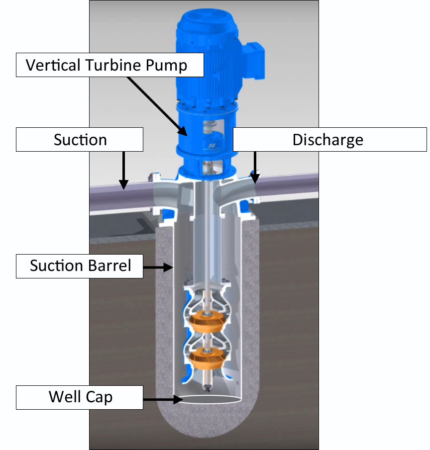
Figure 1. Deep well booster pump diagram
The vertical turbine pump is installed via bolts; it can be removed for integrity assessments fairly simply. However, the buried suction barrel requires complete excavation to inspect using traditional methods. This inspection process was expensive, time-consuming, and risked damaging the barrel. For these reasons, the pipeline operator contacted Diakont to develop a new robotic solution to inspect the barrels in situ. For the initial inspection project, the pipeline operator identified two suction barrels 12’ deep with diameters between 20” and 40”.
Inspection Solution
The walls of the suction barrels have the same characteristics as a vertical unpiggable pipe section. Diakont’s standard robotic in-line inspection (ILI) crawler was identified to handle the integrity assessment of this section.
The bi-directional crawler employs three tank-like tracks; two at the bottom of the tool for primary propulsion, and a third upper track that extends to stabilize the tool in difficult geometries such as bends, inclined, and vertical segments. See Figure 2.
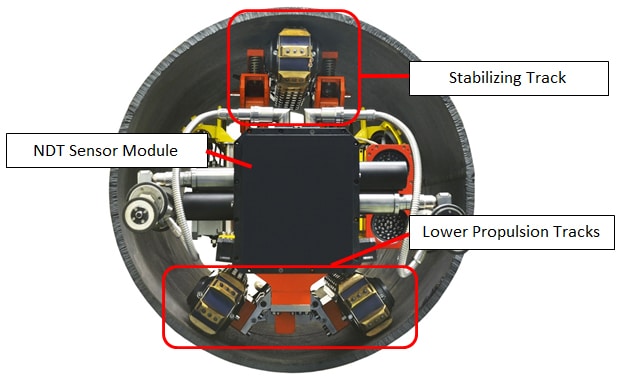
Figure 2. Unpiggable ILI crawler track configuration
Diakont’s robotic crawler uses an integrated sensor suite to assess pipe wall integrity:
- Ultrasonic testing (UT) electromagnetic acoustic transducers (EMAT) measure pipeline wall thickness.
- A laser profilometer creates detailed mapping of the pipeline’s inner surface as well as detects and measures internal surface irregularities such as pitting.
- High-definition cameras allow technicians to gather photographs and video of the pipeline interior.
Unlike conventional UT instruments, the EMAT instrument does not require liquid couplant between the transducers and the pipe body to transmit ultrasonic signals, making it ideal for inspections where liquid within the lines is impractical or unacceptable. All sensor data feeds back to the inspection technicians in real time via an umbilical cable and pipeline operators are given same-day assessment results.
New Tooling Development
The well cap at the bottom of the suction barrel could not be inspected with Diakont’s standard ILI tooling, which rotates the EMAT transducers circumferentially to scan pipe walls as shown in Figure 2. The NDT module design had to be modified so that the sensors could make contact with the bottom plate.
Diakont’s engineering group accomplished this by mounting the sensors on a linear actuator on the front of the module to move the sensors across the surface area of the well cap (see figure 3). This NDT module modification accommodated both EMAT and laser profilometry sensor suites.
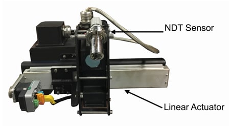
Figure 3. NDT sensor mounted on linear actuator for well cap inspections
Tool Testing
Diakont built two in-house mockups of the deep well suction barrels to test and verify the sensor modifications for the different can diameters (see Figure 4). The mockup barrels were also used to train inspection technicians on new crane and inspection tool operating procedures before deploying to the customer site.
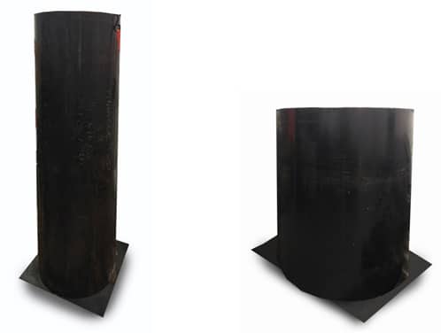
Figure 4. Suction barrel mockups (20” at left, 36”-40” at right)
Inspection Procedure
The pipeline operator identified two deep well suction barrels for the initial inspection project. The first suction barrel was 20” in diameter and 12’ deep. The second suction barrel was 36” in diameter at the opening, with a reducer located 10.75’ down widening to 40” diameter for the last 6’ to the well cap.
Before the inspection team deployed to the facility, the pipeline operator shut down the pipe system and removed the vertical turbine pumps. Each well was cleaned using a high-pressure water jet system to expose the well barrel and cap surfaces for inspection signal integrity; the laser profilometer sensor cannot scan through any sludge or debris, while cleaning is recommended to mitigate signal noise during EMAT inspection.
When working near the wells, technicians secured themselves with a safety harness and tether to prevent injuries from falling down the wells. A lifting crane was installed above each well to help orient the robotic crawlers before beginning each tool run (see figure 5). Inspection technicians lowered the crawlers into the wells and extended the tracks into the well walls, holding the crawlers rigidly in place.
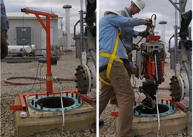
Figure 5. Robot positioning crane
Inspection technicians scanned the well caps first to avoid dislodging any remnant debris from the well barrel onto the bottom and reducing data quality. Technicians scanned the well cap in circular patterns beginning at the center of the cap, then stepping out the linear actuator to scan the next ring until 100% of the cap surface was inspected – figure 6 shows the well cap next to the concentric rings of the laser profilometer scans.
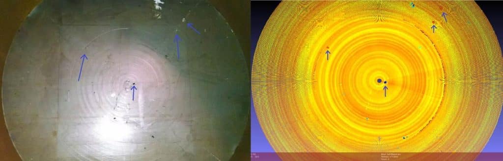
Figure 6. Well cap compared to the laser profilometry scans
Inspection Results
The 20” diameter suction barrel inspection revealed a 2” gouge in the steel bar that bisected the well cap; Figure 7 shows a photograph of the gouge, while Figure 8 shows the Diakont laser profilometry scan of the gouge. In the same suction barrel, deformation was discovered at distance of 4.4’ above the well cap (see Figure 9). On the second suction barrel, the robotic crawler successfully navigated the reducer to inspect the barrel wall and the well cap. No significant issues or metal loss were detected while inspecting the section suction barrel; remaining wall thickness measurements were all above the thresholds of 0.1604” for the well barrel and 1.887” for the well cap.
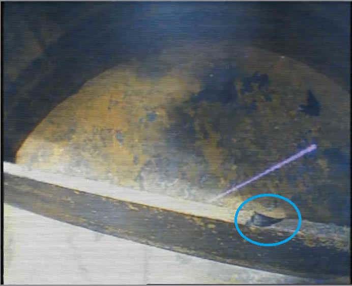
Figure 7. Gouge on steel bar bisecting the well cap
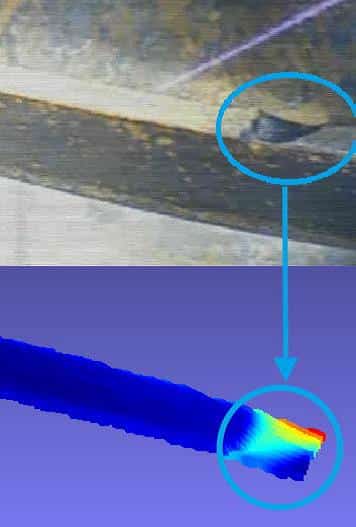
Figure 7. Gouge on steel bar bisecting the well cap
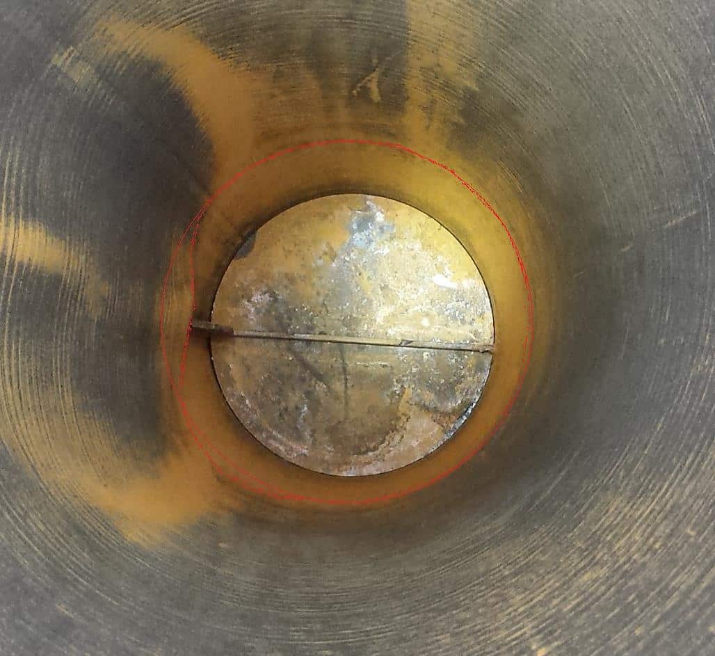
Figure 9. Deformation at 4.4’ above the well cap
Diakont Advanced Technologies successfully used a robotic crawler to inspect the condition of unpiggable natural gas pipelines running underneath the Hudson River for pipeline operator Williams. This robotic crawler uses rugged track systems to traverse difficult pipe geometries and inspect lines that are inaccessible to traditional flow-driven, smart pig tools.
Challenge
- Inspect the condition of an unpiggable natural gas pipeline running underneath the Hudson River for pipeline operator Williams.
Solution
- Implement Diakont’s robotic crawler to inspect the interior of the challenging pipeline.
Results
- The pipeline inspections went smoothly, the lines were in excellent condition and completed ahead of schedule. Williams took advantage of the inspection crews extra availability and arranged another inspection for a 8000’ pipeline that was beyond the original project scope.
New Urban Development Creating HCA
Construction of new apartment buildings and condominiums within urban areas creates new high consequence areas (HCA) in existing pipelines. Some of the unpiggable pipelines within these HCAs have never been inspected using inline inspection tools and now require integrity management programs from the Pipeline and Hazardous Materials Safety Administration (PHMSA). This was the situation that Williams faced when new apartment buildings were constructed on the edge of the Hudson River near Williams’ Transco pipeline system in New Jersey.
Self-Propelled Solution
The HCA piping inspected by Williams consists of two 24” lines running parallel to each other underneath the Hudson River. With no external access to the pipeline, Williams integrity engineers turned to in-line inspection solutions. Compounding the inspection challenges, Williams only had access to the pipe on one side of the Hudson River, so the inspection tool would have to enter and exit the pipe from the same location, ruling out traditional smart pigs, which require retrieval from the end of the line following inspections.
Williams identified Diakont’s robotic crawler as a potential solution to meet the inspection challenges. The bidirectional crawler employs three tank-like tracks: two at the bottom of the tool for primary propulsion, and a third upper track that extends out as necessary to stabilize the tool in difficult geometries such as bends and inclined pipes.
Diakont’s robotic crawler uses an integrated sensor suite to assess pipe wall integrity:
- An ultrasonic testing (UT) electromagnetic acoustic transducer (EMAT) measures pipeline wall thickness.
- A laser profilometer (LPM) creates detailed mapping of the pipeline’s inner surface, as well as detects and measures internal surface irregularities such as pitting.
- High-definition cameras allow technicians to gather photographs and video of the appearance of the pipeline’s interior.
Unlike conventional UT instruments that require a liquid couplant between the transducers and pipe body to transmit ultrasonic signals, the EMAT instrument does not require any couplant, making it ideal for gas pipeline inspections where adding liquid within lines is avoided at all costs. All sensor data feeds back to the inspection technicians in real time via an umbilical cable and pipeline operators are given same-day assessment results.
After a live demonstration of the robotic crawler’s capabilities in a 24” pipe mockup, Williams selected Diakont’s robotic crawler for the urban pipeline inspection.
In-Line Inspection
Williams prepared for inspection operations by removing tees in the valve yard near the edge of the Hudson River to create access points for each buried pipeline. Williams also installed temporary vertical leg sections on the pipelines to bring the access points above the water level.
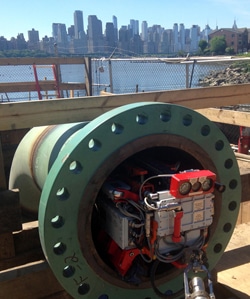
Figure 1. Robotic crawler positioned at access point created on Transco Pipeline
Aside from making the pipeline entry point more accessible, installing the pipe extensions also decreased the risk of getting water in the line during the inspection. After installing the extensions, Williams blew the lines dry to remove remaining product and excess condensation.
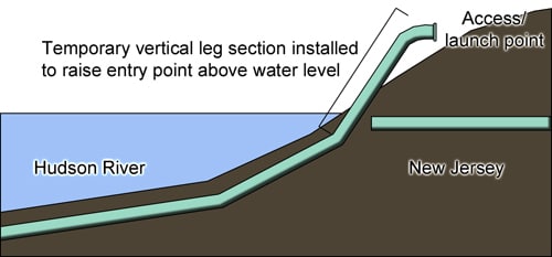
Figure 2. Diagram of extension legs installed on gas lines to raise access point above water level
Diakont mobilized two inspection teams with two robotic crawler tools to inspect the twin gas lines simultaneously and minimize pipeline downtime. Both of the robotic crawlers were hand-loaded into the pipes and driven through the entire inspection length while taking video of the interior and surveying pipe elements. Technicians then reversed the crawlers back to the launch point and exchanged the high-definition video modules for EMAT sensors to inspect the pipe in autoscan mode. After completing the automatic scan, inspection technicians manually drove the robotic crawlers to every indication of a potential defect for detailed characterization. Throughout the inspection, NDE data analysts reviewed the resultant data in real time, monitored tool operation via telemetry, and recorded precise pipeline geometric data, which was incorporated into a pipe tally in the pipe feature list report.
Inspection Results
The pipeline inspections went smoothly and the lines were completed ahead of schedule. Williams took advantage of the extra availability of the inspection crews and arranged inspection of an additional 800’ of pipeline beyond the original project scope.
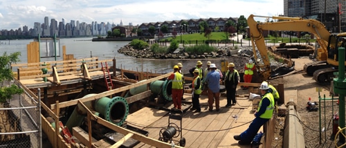
Figure 3. Inspection site photo with robotic crawlers deployed into the twin gas lines
The integrity assessment of the Transco pipeline sections showed the pipe to be in excellent condition. The only abnormalities uncovered during the inspections were a few small pieces of wax on the lower region of the pipe. The following pictures of this wax (see Figure 4) were taken by the inspection crew during the initial pipeline survey using the tool’s high-definition camera.
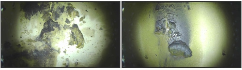
Figure 4. Wax found in the lower regions of the pipeline
With the pipeline integrity validated, Williams made plans to put the pipeline back in service. Williams also made plans to install permanent tees to the pipelines to facilitate future inspections without requiring any excavation or temporary leg installations. According to James Harrison, manager at Asset Integrity, the robotic tool helps solve a problem that has been plaguing the pipeline industry for years. “The smart pig is one of the most crucial tools we have to ensure pipeline integrity. Unfortunately, not all pipes are piggable,” James says. “This new robotic crawler tool gives us access to pipe sections which had never before been candidates for in-line inspection.”
Authors:
Casey Lajaunie, Supervisor, Asset Integrity at Williams and
Jonathan Minder, ILI Solutions Engineer at Diakont